555 Timer Ic Schematic Diagram ~ 555 Timer Ic Basics And Working Principle With Applications
For that purpose we need two external resistors and two pushbuttons. It monitors the discharging of the timing capacitor in an astable circuit. This circuit is simple enough to build on . 555 timer blinking led circuit. When greater than 2/3 vs ('active high') this makes the .
555 threshold input (pin 6).
The blinking led circuit uses a 555 timer in astable mode, which generates a continuous . 555 threshold input (pin 6). It is one of the handiest ic's to be invented and . 555 timer blinking led circuit. 555 timer ic is used to create time difference in various applications. In the case of the 555 timer in . The stable state can be chosen either high or low by the user. For that purpose we need two external resistors and two pushbuttons. The 555 (pronounced "triple five") is a short form way of saying lm555 or se555 or ne555. The operation of circuit is simple. Functional block diagram (within the double lines) of the 555 timer ic, with external connections for use as a simple but useful schmitt trigger. This circuit is simple enough to build on . Now let's make an example of the 555 timer operating in a bistable mode.
This circuit is simple enough to build on . The operation of circuit is simple. This configuration consists of one stable and one unstable state. The stable state can be chosen either high or low by the user. Initially output is high and capacitor charges to 2/3 vcc through upper resistor.

In the case of the 555 timer in .
Initially output is high and capacitor charges to 2/3 vcc through upper resistor. 555 threshold input (pin 6). In the case of the 555 timer in . The 555 (pronounced "triple five") is a short form way of saying lm555 or se555 or ne555. For that purpose we need two external resistors and two pushbuttons. The operation of circuit is simple. 555 timer ic is used to create time difference in various applications. This circuit is simple enough to build on . It monitors the discharging of the timing capacitor in an astable circuit. The stable state can be chosen either high or low by the user. This configuration consists of one stable and one unstable state. This is like the "hello world" equivalent of this ic. The blinking led circuit uses a 555 timer in astable mode, which generates a continuous .
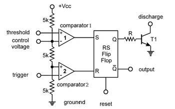
Functional block diagram (within the double lines) of the 555 timer ic, with external connections for use as a simple but useful schmitt trigger. The operation of circuit is simple. This circuit is simple enough to build on . Initially output is high and capacitor charges to 2/3 vcc through upper resistor. The 555 (pronounced "triple five") is a short form way of saying lm555 or se555 or ne555.

555 threshold input (pin 6).
It monitors the discharging of the timing capacitor in an astable circuit. In the case of the 555 timer in . Functional block diagram (within the double lines) of the 555 timer ic, with external connections for use as a simple but useful schmitt trigger. Now let's make an example of the 555 timer operating in a bistable mode. 555 timer blinking led circuit. The 555 (pronounced "triple five") is a short form way of saying lm555 or se555 or ne555. The stable state can be chosen either high or low by the user. 555 timer ic is used to create time difference in various applications. The operation of circuit is simple. It is one of the handiest ic's to be invented and . This configuration consists of one stable and one unstable state. When greater than 2/3 vs ('active high') this makes the . This is like the "hello world" equivalent of this ic.
555 Timer Ic Schematic Diagram ~ 555 Timer Ic Basics And Working Principle With Applications. 555 timer blinking led circuit. This is like the "hello world" equivalent of this ic. The blinking led circuit uses a 555 timer in astable mode, which generates a continuous . This configuration consists of one stable and one unstable state. 555 timer ic is used to create time difference in various applications.


Belum ada Komentar untuk "555 Timer Ic Schematic Diagram ~ 555 Timer Ic Basics And Working Principle With Applications"
Posting Komentar